跳至内容
跳至内容 
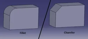
The choice between a fillet and a chamfer is a subtle yet critical decision. The two edge treatments serve far more than aesthetic purposes in engineering design.
They may seem somewhat interchangeable at first. However, fillets and chamfers are highly different from one another. Your ultimate choice between the two can significantly impact cost efficiency, integrity, safety, and visuals.
Therefore, this article brings up the strategic implications of edge selection. You can explore how to make the right choice to turn a design into something exceptional.
Fillet Overview
It indicates a rounded interior/exterior corner applied to a product’s edge. In CAD and CNC, fillets are defined by their radius. The numeric value equals the curvature of the transition between surfaces.

Fillets are readily applied to mechanical designs. Designers tend to choose fillets to –
- External edges to improve ergonomics and appearance.
- Internal corners to prevent cracking under load.
- Fluid pathways to reduce turbulence and improve flow.
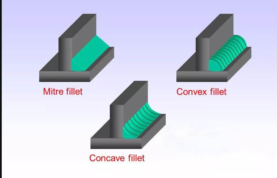
Standard Fillet Types
- Concave Fillet: It features a rounded inward corner between two surfaces (internal joints, stress relief zones).
- Convex Fillet: It features a rounded outward edge or corner (external edges, ergonomic surfaces).
- Edge Fillet: It gets applied along the edge of a part/item for safety, aesthetics, and handling comfort.
- Full-Round Fillet: It marks a smooth transition between three surfaces forming a continuous curve (high-flow fluid systems, aerodynamic parts).
- Face Fillet: It’s applied between two adjacent faces in CAD modeling (complex surface transitions).
Advantages of Fillets
- Stress Reduction: Fillets eliminate sharp corners to improve fatigue resistance. Filleted joints can reduce stress by up to 60% compared to sharp corners.
- Improved Durability: Rounded transitions distribute forces more evenly. It extends the lifespan of parts in aerospace, automotive, and structural applications.
- Machining Efficiency: Fillets reduce tool wear and allow smoother tool paths in CNC. The design ultimately reduces production time and cost.
- Assembly Ease: Rounded edges facilitate part alignment and reduce damage during assembly. It’s beneficial in tight-tolerance systems.
- Safety and Ergonomics: Fillets minimize injury risk by softening edges. It seems critical in consumer products, medical devices, and handheld tools.
- Aesthetic Appeal: Filleted edges offer a sleek, modern, and polished look. No wonder they get into industrial design and consumer electronics.
Limitations of Fillets
- Increased Machining Complexity: Fillets may require specialized tooling or multi-axis machining for precision parts.
- Material Waste: Larger fillet radii can lead to excess material removal. It impacts sustainability in high-volume production.
- Design Trade-offs: Overuse of fillets may soften the visual impact. Such actions can reduce the part’s sharpness/precision.
- Assembly Fit Issues: Fillets can interfere with mating surfaces or fastener placement when improperly implemented.
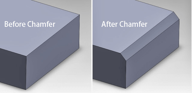
Chamfer Overview
It indicates an angled but flat surface to replace a sharp 90° corner between two adjoining surfaces. A chamfer introduces a straight bevel. The standard angle is 45° for most cases, though 30°, 60°, or custom values are also available.
Chamfers have widespread applications in machining, CAD modeling, and product design. They can –
- Facilitate assembly.
- Improve safety.
- Enhance aesthetics.
- Prevent edge damage.
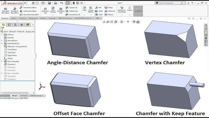
Common Chamfer Type
- Standard Chamfer (45°): It comes with equal bevel along two surfaces at 45° in brackets, enclosures, and flat parts.
- Distance and Angle Chamfer: It’s defined by a linear offset and a custom angle (30°or 60°) in precision assemblies, guided insertions.
- Two-Distance Chamfer: Unequal bevels on adjacent surfaces form an asymmetric angle (clearance management, complex mating surfaces).
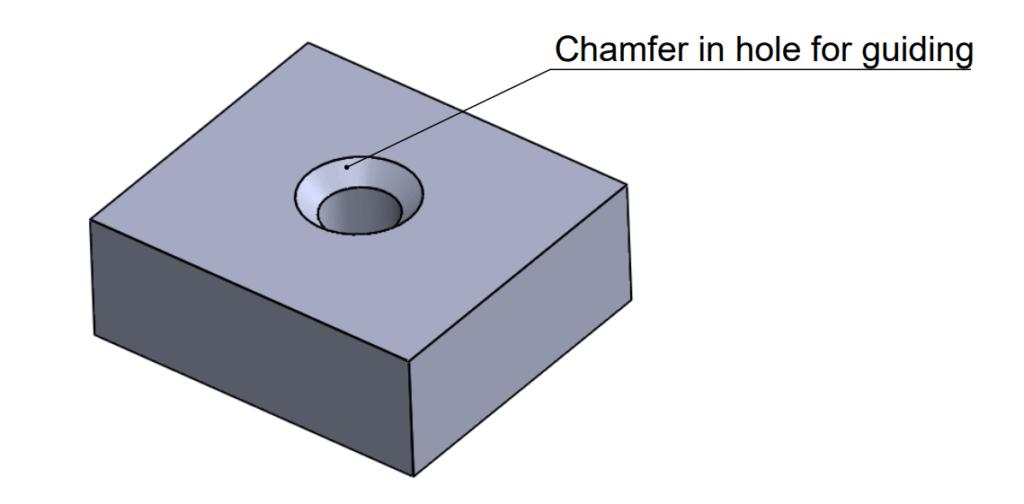
- Chamfered Hole: It features a beveled edge around a drilled or tapped hole, like in screw insertion, countersinking, and fastener fit.
- Break Edge Chamfer: Minimal chamfer removes burrs or sharpness for safety, inspection, and post-processing.
Advantages of Chamfers
- Assembly Efficiency: Chamfers guide mating parts, fasteners, and tools into position more easily. In automated assembly, they reduce misalignment and improve throughput.
- Edge Protection: Chamfering distributes stress more evenly. It minimizes cracking and chipping in brittle materials.
- Safety Enhancement: Chamfered edges reduce the risk of cuts/injuries during handling, maintenance, or inspection.
- Stress Distribution: Chamfers reduce localized stress in load-bearing or high-vibration environments.
- Surface Treatment Optimization: Chamfered edges improve coating uniformity in anodizing, painting, and powder coating.
- Visual Appeal: Chamfers create crisp, clean lines that convey precision and professionalism in consumer electronics.
- Inspection and Metrology: Chamfers are easier to probe and measure, aiding in CMM inspection and manual gauging.
Limitations of Chamfers
- Reduced Stress Relief: Chamfers don’t distribute stress as effectively as fillets in fatigue-prone components.
- Tooling Complexity: Custom chamfer angles or asymmetric profiles may require specialized tooling.
- Fit Interference: In tight-tolerance assemblies, chamfers can interfere with mating surfaces or fastener heads.
- Aesthetic Trade-offs: Chamfers may lack the softness or ergonomic appeal of fillets in consumer-facing products.
- Material Removal: Chamfering removes more material, which can become a concern in light or cost-sensitive designs.
Chamfer vs Fillet: Key Differences
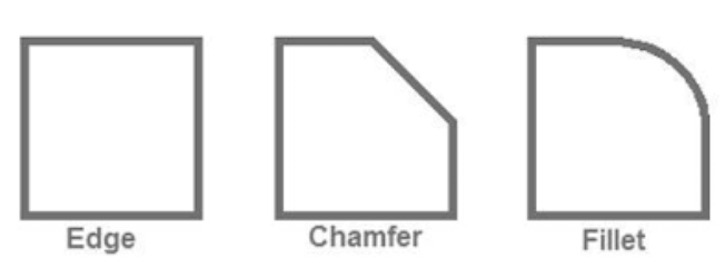
A. Shape/Geometry
A fillet introduces a rounded transition between two intersecting surfaces by a radius (R). It creates a smooth and curved edge that blends surfaces seamlessly.
A chamfer replaces a sharp corner with a flat yet angled surface (usually at 45°). However, other angles (30° or 60°) are also possible to form a straight bevel.
B. Manufacturing Ease
Fillet requires ball-end mills or multi-axis machining for internal curves. It may increase tool wear and machining time for tight radii. Filleting is common in CNC milling, injection molding, and die casting.
Chamfer is easy and fast to machine using standard end mills. It’s ideal for manual machining, sheet metal, and 3D printing. Proper chamfering can reduce the post-processing time by eliminating burrs.
C. Stress Handling
Fillet holds the upper hand by distributing the load across a curved surface. It seems a must in load-bearing components. The geometry even enhances the fatigue resistance and structural integrity.
Chamfer offers limited stress relief. It may initiate some stress at the edge if not properly dimensioned. The design is preferred in non-critical zones or where stress is intentionally localized.
D. Aesthetics
Fillet creates a soft and ergonomic look. It’s ideal for consumer electronics, medical devices, and furniture. Filleting can enhance tactile comfort and visual flow.
Chamfer delivers a sharp, technical appearance. Geometry is favored in industrial hardware, enclosures, and precision instruments. It suggests precision and craftsmanship.
E. Assembly Considerations
Fillet may interfere with mating surfaces or fastener heads if not accounted for. The process requires careful tolerance planning in tight assemblies.
Chamfer facilitates alignment and insertion of parts, screws, pins, and dowels. It’s relatively common in hole entries, lead-ins, and snap-fit designs.
F. Cost Factors
Fillet comes with a higher machining cost due to the complexity of the tool and slower feed rates. It may require custom tooling or multi-pass operations.
Chamfer is more cost-effective, especially in high-volume production. The process can notably reduce tool wear and cycle time.
G. CAD, Drawing, Documentation
Fillet gets defined by radius (R) in CAD drawings. It requires tangent continuity and may affect surface modeling in complex geometries. In GD&T, fillets are often referenced for stress-critical zones.
Chamfer gets specified by distance and angle. They’re easier to document and inspect using CMMs and manual gauges. It’s preferred in technical drawings for fasteners, holes, and mating edges.
Fillet vs Chamfer: Comparison Table
| Criteria or Aspect | Fillet | Chamfer |
| Shape/Geometry | Rounded transition between surfaces by a radius | Flat, angled surface replacing a sharp corner |
| Stress Handling | Reduced stress concentrations and improved fatigue life | Limited stress relief; may concentrate some stress |
| Manufacturing Ease | Ball-end mills or multi-axis machining; slower tool paths | Easy to machine; faster and more cost-effective |
| Assembly Considerations | Potential interference with mating surfaces or fasteners | Facilitate alignment and insertion |
| Aesthetic Impact | Smooth, ergonomic appearance | Sharp, precise look |
| Safety and Ergonomics | Reduced injury risk; comfy to touch and handle | Minimized sharp edges; safer than raw corners |
| Cost Factors | Higher machining cost due to complexity and tool wear | Lower cost; reduces cycle time and tooling requirements |
| CAD and Documentation | Compromised surface continuity in complex models | Defined by angle and/or distances; easy to inspect |
| Use in Fluid Dynamics | Improved flow by reducing turbulence | Less effective in fluid systems |
| Common Applications | Aerospace joints, automotive brackets, consumer electronics, and medical tools | Fastener holes, enclosures, sheet metal parts, and mechanical guides |
Fillet or Chamfer: How to Choose the Right Edge?
Don’t take the choice like a minor design decision. Negligence can significantly impact a product’s performance, manufacturability, safety, cost, and aesthetics.
A. Choose Fillet when –
- The part is subject to cyclic loading, vibration, or high stress.
- Structural integrity and fatigue resistance are mandatory.
- You need to reduce stress concentrations at internal corners.
B. Choose Chamfer when –
- You need a clean break or an angled surface.
- Stress relief is not a priority.
- The part is primarily used for guiding, mating, or alignment.
Conclusion
Fillets induce strength, smoothness, and relief for parts that demand durability and ergonomic finesse. Chamfers deliver easy manufacturing, sharpness, and assembly for precision and speed. But this isn’t a binary choice. You must strike a balance between functionality, cost-efficiency, and visuals.
Get the Ultimate Precision for Designs with HRC
Ensure the best possible outcome for your CNC machining specs with HRC. We have been leading the industry with practical, exact, and efficient solutions for 17+ years. Contact us for more from the experts.
Frequently Asked Questions (FAQs)
- When should I use a fillet instead of a chamfer?
Use fillets for stress relief, fatigue resistance, and ergonomic design. It’s mainly in load-bearing or consumer-facing parts.
- Is a chamfer easier to machine than a fillet?
Yes. Chamfers require simpler tooling and fewer passes. It makes the process faster and more cost-effective to produce.
- Do fillets improve part strength more than chamfers?
Yes (for the most part). Fillets can distribute stress over a wider area. It reduces the risk of cracking or fatigue failure.
- Which edge treatment is better for 3D printing?
Chamfers are often preferred for overhangs and support-free printing. Meanwhile, fillets can enhance strength and improve the surface finish.